Product Description
Our CZPT chain was produced by machinery processing from raw materials to finished products and a full set of quality testing equipment. Mechanical processing equipment include grinding machines, high speed punching machines, milling machines, high speed automatic rolling and assembling machine. Heat treatment was processed by continuous mesh belt conveyor furnace, mesh belt conveyor annealing furnace, advanced central control system of heat treatment, rotary CZPT for chain component heat treatment, which ensure the stability and consistency of the key function of chain components.
We are the best suppliers of Chinese largest palletizing robot enterprises. These items are durable quality with affordable prices, replace of Japan chains, ZheJiang chains exported to Europe, America, Asia and other countries and regions..
| Model No. | 08A-1--48A-1 |
| Usage | Transimission chain |
| Feature | Heat treatment |
| Tensile Strength | 1.8kn-3750kn |
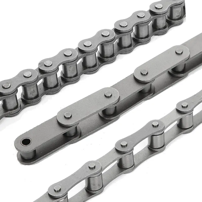
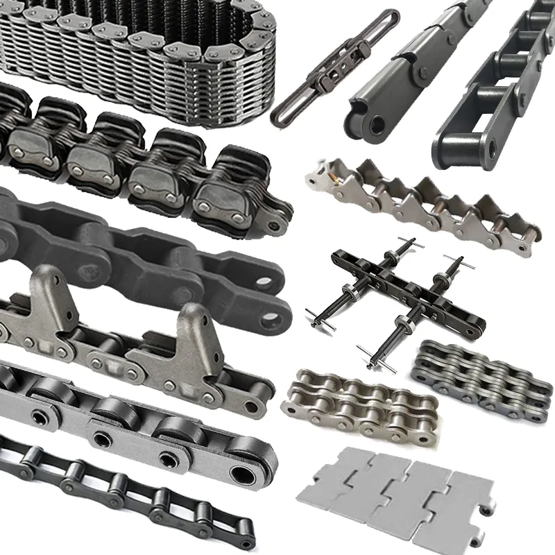
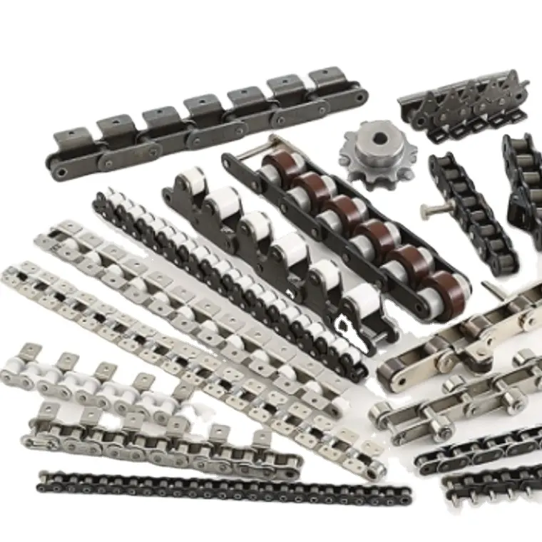
Chain Pictures
ROLLER CHAIN
Roller chain or bush roller chain is the type of chain drive most commonly used for transmission of mechanical power on many kinds of domestic, industrial and agricultural machinery, including conveyors, wire- and tube-drawing machines, printing presses, cars, motorcycles, and bicycles. It consists of a series of short cylindrical rollers held together by side links. It is driven by a toothed wheel called a sprocket. It is a simple, reliable, and efficient means of power transmission.
CONSTRUCTION OF THE CHAIN
Two different sizes of roller chain, showing construction.
There are 2 types of links alternating in the bush roller chain. The first type is inner links, having 2 inner plates held together by 2 sleeves or bushings CZPT which rotate 2 rollers. Inner links alternate with the second type, the outer links, consisting of 2 outer plates held together by pins passing through the bushings of the inner links. The “bushingless” roller chain is similar in operation though not in construction; instead of separate bushings or sleeves holding the inner plates together, the plate has a tube stamped into it protruding from the hole which serves the same purpose. This has the advantage of removing 1 step in assembly of the chain.
The roller chain design reduces friction compared to simpler designs, resulting in higher efficiency and less wear. The original power transmission chain varieties lacked rollers and bushings, with both the inner and outer plates held by pins which directly contacted the sprocket teeth; however this configuration exhibited extremely rapid wear of both the sprocket teeth, and the plates where they pivoted on the pins. This problem was partially solved by the development of bushed chains, with the pins holding the outer plates passing through bushings or sleeves connecting the inner plates. This distributed the wear over a greater area; however the teeth of the sprockets still wore more rapidly than is desirable, from the sliding friction against the bushings. The addition of rollers surrounding the bushing sleeves of the chain and provided rolling contact with the teeth of the sprockets resulting in excellent resistance to wear of both sprockets and chain as well. There is even very low friction, as long as the chain is sufficiently lubricated. Continuous, clean, lubrication of roller chains is of primary importance for efficient operation as well as correct tensioning.
LUBRICATION
Many driving chains (for example, in factory equipment, or driving a camshaft inside an internal combustion engine) operate in clean environments, and thus the wearing surfaces (that is, the pins and bushings) are safe from precipitation and airborne grit, many even in a sealed environment such as an oil bath. Some roller chains are designed to have o-rings built into the space between the outside link plate and the inside roller link plates. Chain manufacturers began to include this feature in 1971 after the application was invented by Joseph Montano while working for Whitney Chain of Hartford, Connecticut. O-rings were included as a way to improve lubrication to the links of power transmission chains, a service that is vitally important to extending their working life. These rubber fixtures form a barrier that holds factory applied lubricating grease inside the pin and bushing wear areas. Further, the rubber o-rings prevent dirt and other contaminants from entering inside the chain linkages, where such particles would otherwise cause significant wear.[citation needed]
There are also many chains that have to operate in dirty conditions, and for size or operational reasons cannot be sealed. Examples include chains on farm equipment, bicycles, and chain saws. These chains will necessarily have relatively high rates of wear, particularly when the operators are prepared to accept more friction, less efficiency, more noise and more frequent replacement as they neglect lubrication and adjustment.
Many oil-based lubricants attract dirt and other particles, eventually forming an CZPT paste that will compound wear on chains. This problem can be circumvented by use of a “dry” PTFE spray, which forms a solid film after application and repels both particles and moisture.
VARIANTS DESIGN
Layout of a roller chain: 1. Outer plate, 2. Inner plate, 3. Pin, 4. Bushing, 5. Roller
If the chain is not being used for a high wear application (for instance if it is just transmitting motion from a hand-operated lever to a control shaft on a machine, or a sliding door on an oven), then 1 of the simpler types of chain may still be used. Conversely, where extra strength but the smooth drive of a smaller pitch is required, the chain may be “siamesed”; instead of just 2 rows of plates on the outer sides of the chain, there may be 3 (“duplex”), 4 (“triplex”), or more rows of plates running parallel, with bushings and rollers between each adjacent pair, and the same number of rows of teeth running in parallel on the sprockets to match. Timing chains on automotive engines, for example, typically have multiple rows of plates called strands.
Roller chain is made in several sizes, the most common American National Standards Institute (ANSI) standards being 40, 50, 60, and 80. The first digit(s) indicate the pitch of the chain in eighths of an inch, with the last digit being 0 for standard chain, 1 for lightweight chain, and 5 for bushed chain with no rollers. Thus, a chain with half-inch pitch would be a #40 while a #160 sprocket would have teeth spaced 2 inches apart, etc. Metric pitches are expressed in sixteenths of an inch; thus a metric #8 chain (08B-1) would be equivalent to an ANSI #40. Most roller chain is made from plain carbon or alloy steel, but stainless steel is used in food processing machinery or other places where lubrication is a problem, and nylon or brass are occasionally seen for the same reason.
Roller chain is ordinarily hooked up using a master link (also known as a connecting link), which typically has 1 pin held by a horseshoe clip rather than friction fit, allowing it to be inserted or removed with simple tools. Chain with a removable link or pin is also known as cottered chain, which allows the length of the chain to be adjusted. Half links (also known as offsets) are available and are used to increase the length of the chain by a single roller. Riveted roller chain has the master link (also known as a connecting link) “riveted” or mashed on the ends. These pins are made to be durable and are not removable.
USE
An example of 2 ‘ghost’ sprockets tensioning a triplex roller chain system
Roller chains are used in low- to mid-speed drives at around 600 to 800 feet per minute; however, at higher speeds, around 2,000 to 3,000 feet per minute, V-belts are normally used due to wear and noise issues.
A bicycle chain is a form of roller chain. Bicycle chains may have a master link, or may require a chain tool for removal and installation. A similar but larger and thus stronger chain is used on most motorcycles although it is sometimes replaced by either a toothed belt or a shaft drive, which offer lower noise level and fewer maintenance requirements.
The great majority of automobile engines use roller chains to drive the camshaft(s). Very high performance engines often use gear drive, and starting in the early 1960s toothed belts were used by some manufacturers.
Chains are also used in forklifts using hydraulic rams as a pulley to raise and lower the carriage; however, these chains are not considered roller chains, but are classified as lift or leaf chains.
Chainsaw cutting chains superficially resemble roller chains but are more closely related to leaf chains. They are driven by projecting drive links which also serve to locate the chain CZPT the bar.
Sea Harrier FA.2 ZA195 front (cold) vector thrust nozzle – the nozzle is rotated by a chain drive from an air motor
A perhaps unusual use of a pair of motorcycle chains is in the Harrier Jump Jet, where a chain drive from an air motor is used to rotate the movable engine nozzles, allowing them to be pointed downwards for hovering flight, or to the rear for normal CZPT flight, a system known as Thrust vectoring.
WEAR
The effect of wear on a roller chain is to increase the pitch (spacing of the links), causing the chain to grow longer. Note that this is due to wear at the pivoting pins and bushes, not from actual stretching of the metal (as does happen to some flexible steel components such as the hand-brake cable of a motor vehicle).
With modern chains it is unusual for a chain (other than that of a bicycle) to wear until it breaks, since a worn chain leads to the rapid onset of wear on the teeth of the sprockets, with ultimate failure being the loss of all the teeth on the sprocket. The sprockets (in particular the smaller of the two) suffer a grinding motion that puts a characteristic hook shape into the driven face of the teeth. (This effect is made worse by a chain improperly tensioned, but is unavoidable no matter what care is taken). The worn teeth (and chain) no longer provides smooth transmission of power and this may become evident from the noise, the vibration or (in car engines using a timing chain) the variation in ignition timing seen with a timing light. Both sprockets and chain should be replaced in these cases, since a new chain on worn sprockets will not last long. However, in less severe cases it may be possible to save the larger of the 2 sprockets, since it is always the smaller 1 that suffers the most wear. Only in very light-weight applications such as a bicycle, or in extreme cases of improper tension, will the chain normally jump off the sprockets.
The lengthening due to wear of a chain is calculated by the following formula:
M = the length of a number of links measured
S = the number of links measured
P = Pitch
In industry, it is usual to monitor the movement of the chain tensioner (whether manual or automatic) or the exact length of a drive chain (one rule of thumb is to replace a roller chain which has elongated 3% on an adjustable drive or 1.5% on a fixed-center drive). A simpler method, particularly suitable for the cycle or motorcycle user, is to attempt to pull the chain away from the larger of the 2 sprockets, whilst ensuring the chain is taut. Any significant movement (e.g. making it possible to see through a gap) probably indicates a chain worn up to and beyond the limit. Sprocket damage will result if the problem is ignored. Sprocket wear cancels this effect, and may mask chain wear.
CHAIN STRENGTH
The most common measure of roller chain’s strength is tensile strength. Tensile strength represents how much load a chain can withstand under a one-time load before breaking. Just as important as tensile strength is a chain’s fatigue strength. The critical factors in a chain’s fatigue strength is the quality of steel used to manufacture the chain, the heat treatment of the chain components, the quality of the pitch hole fabrication of the linkplates, and the type of shot plus the intensity of shot peen coverage on the linkplates. Other factors can include the thickness of the linkplates and the design (contour) of the linkplates. The rule of thumb for roller chain operating on a continuous drive is for the chain load to not exceed a mere 1/6 or 1/9 of the chain’s tensile strength, depending on the type of master links used (press-fit vs. slip-fit)[citation needed]. Roller chains operating on a continuous drive beyond these thresholds can and typically do fail prematurely via linkplate fatigue failure.
The standard minimum ultimate strength of the ANSI 29.1 steel chain is 12,500 x (pitch, in inches)2. X-ring and O-Ring chains greatly decrease wear by means of internal lubricants, increasing chain life. The internal lubrication is inserted by means of a vacuum when riveting the chain together.
CHAIN STHangZhouRDS
Standards organizations (such as ANSI and ISO) maintain standards for design, dimensions, and interchangeability of transmission chains. For example, the following Table shows data from ANSI standard B29.1-2011 (Precision Power Transmission Roller Chains, Attachments, and Sprockets) developed by the American Society of Mechanical Engineers (ASME). See the references[8][9][10] for additional information.
ASME/ANSI B29.1-2011 Roller Chain Standard SizesSizePitchMaximum Roller DiameterMinimum Ultimate Tensile StrengthMeasuring Load25
| ASME/ANSI B29.1-2011 Roller Chain Standard Sizes | ||||
| Size | Pitch | Maximum Roller Diameter | Minimum Ultimate Tensile Strength | Measuring Load |
|---|---|---|---|---|
| 25 | 0.250 in (6.35 mm) | 0.130 in (3.30 mm) | 780 lb (350 kg) | 18 lb (8.2 kg) |
| 35 | 0.375 in (9.53 mm) | 0.200 in (5.08 mm) | 1,760 lb (800 kg) | 18 lb (8.2 kg) |
| 41 | 0.500 in (12.70 mm) | 0.306 in (7.77 mm) | 1,500 lb (680 kg) | 18 lb (8.2 kg) |
| 40 | 0.500 in (12.70 mm) | 0.312 in (7.92 mm) | 3,125 lb (1,417 kg) | 31 lb (14 kg) |
| 50 | 0.625 in (15.88 mm) | 0.400 in (10.16 mm) | 4,880 lb (2,210 kg) | 49 lb (22 kg) |
| 60 | 0.750 in (19.05 mm) | 0.469 in (11.91 mm) | 7,030 lb (3,190 kg) | 70 lb (32 kg) |
| 80 | 1.000 in (25.40 mm) | 0.625 in (15.88 mm) | 12,500 lb (5,700 kg) | 125 lb (57 kg) |
| 100 | 1.250 in (31.75 mm) | 0.750 in (19.05 mm) | 19,531 lb (8,859 kg) | 195 lb (88 kg) |
| 120 | 1.500 in (38.10 mm) | 0.875 in (22.23 mm) | 28,125 lb (12,757 kg) | 281 lb (127 kg) |
| 140 | 1.750 in (44.45 mm) | 1.000 in (25.40 mm) | 38,280 lb (17,360 kg) | 383 lb (174 kg) |
| 160 | 2.000 in (50.80 mm) | 1.125 in (28.58 mm) | 50,000 lb (23,000 kg) | 500 lb (230 kg) |
| 180 | 2.250 in (57.15 mm) | 1.460 in (37.08 mm) | 63,280 lb (28,700 kg) | 633 lb (287 kg) |
| 200 | 2.500 in (63.50 mm) | 1.562 in (39.67 mm) | 78,175 lb (35,460 kg) | 781 lb (354 kg) |
| 240 | 3.000 in (76.20 mm) | 1.875 in (47.63 mm) | 112,500 lb (51,000 kg) | 1,000 lb (450 kg |
For mnemonic purposes, below is another presentation of key dimensions from the same standard, expressed in fractions of an inch (which was part of the thinking behind the choice of preferred numbers in the ANSI standard):
| Pitch (inches) | Pitch expressed in eighths |
ANSI standard chain number |
Width (inches) |
|---|---|---|---|
| 1⁄4 | 2⁄8 | 25 | 1⁄8 |
| 3⁄8 | 3⁄8 | 35 | 3⁄16 |
| 1⁄2 | 4⁄8 | 41 | 1⁄4 |
| 1⁄2 | 4⁄8 | 40 | 5⁄16 |
| 5⁄8 | 5⁄8 | 50 | 3⁄8 |
| 3⁄4 | 6⁄8 | 60 | 1⁄2 |
| 1 | 8⁄8 | 80 | 5⁄8 |
Notes:
1. The pitch is the distance between roller centers. The width is the distance between the link plates (i.e. slightly more than the roller width to allow for clearance).
2. The right-hand digit of the standard denotes 0 = normal chain, 1 = lightweight chain, 5 = rollerless bushing chain.
3. The left-hand digit denotes the number of eighths of an inch that make up the pitch.
4. An “H” following the standard number denotes heavyweight chain. A hyphenated number following the standard number denotes double-strand (2), triple-strand (3), and so on. Thus 60H-3 denotes number 60 heavyweight triple-strand chain.
A typical bicycle chain (for derailleur gears) uses narrow 1⁄2-inch-pitch chain. The width of the chain is variable, and does not affect the load capacity. The more sprockets at the rear wheel (historically 3-6, nowadays 7-12 sprockets), the narrower the chain. Chains are sold according to the number of speeds they are designed to work with, for example, “10 speed chain”. Hub gear or single speed bicycles use 1/2″ x 1/8″ chains, where 1/8″ refers to the maximum thickness of a sprocket that can be used with the chain.
Typically chains with parallel shaped links have an even number of links, with each narrow link followed by a broad one. Chains built up with a uniform type of link, narrow at 1 and broad at the other end, can be made with an odd number of links, which can be an advantage to adapt to a special chainwheel-distance; on the other side such a chain tends to be not so strong.
Roller chains made using ISO standard are sometimes called as isochains.
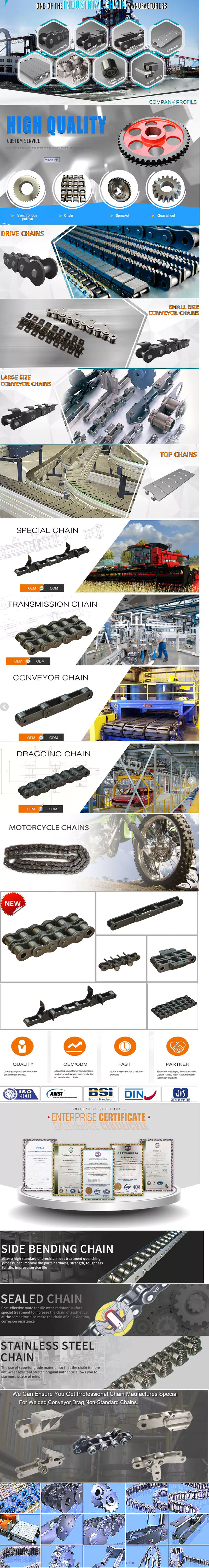
WHY CHOOSE US
1. Reliable Quality Assurance System
2. Cutting-Edge Computer-Controlled CNC Machines
3. Bespoke Solutions from Highly Experienced Specialists
4. Customization and OEM Available for Specific Application
5. Extensive Inventory of Spare Parts and Accessories
6. Well-Developed CZPT Marketing Network
7. Efficient After-Sale Service System
The 219 sets of advanced automatic production equipment provide guarantees for high product quality. The 167 engineers and technicians with senior professional titles can design and develop products to meet the exact demands of customers, and OEM customizations are also available with us. Our sound global service network can provide customers with timely after-sales technical services.
We are not just a manufacturer and supplier, but also an industry consultant. We work pro-actively with you to offer expert advice and product recommendations in order to end up with a most cost effective product available for your specific application. The clients we serve CZPT range from end users to distributors and OEMs. Our OEM replacements can be substituted wherever necessary and suitable for both repair and new assemblies.
|
Shipping Cost:
Estimated freight per unit. |
To be negotiated |
|---|
| Standard or Nonstandard: | Standard |
|---|---|
| Application: | Textile Machinery, Garment Machinery, Conveyer Equipment, Packaging Machinery, Electric Cars, Motorcycle, Food Machinery, Marine, Mining Equipment, Agricultural Machinery, Car |
| Surface Treatment: | Polishing, Oil Blooming |
| Samples: |
US$ 0/Piece
1 Piece(Min.Order) | Order Sample |
|---|
| Customization: |
Available
| Customized Request |
|---|
How do engineering chains compare to other types of chains in terms of efficiency?
Engineering chains are known for their high efficiency in power transmission compared to some other types of chains. Their efficiency can be attributed to several factors:
- Minimal Friction: Engineering chains are designed with precision rollers and bushings, which reduces friction between the chain’s components. This results in less energy loss during power transmission.
- High-Quality Materials: These chains are typically made from high-quality materials, such as alloy steel, which ensures durability and minimal elongation under heavy loads. This material choice helps maintain efficiency over extended periods of use.
- Precise Manufacturing: Engineering chains are manufactured with tight tolerances and precise engineering, ensuring consistent performance and smooth operation. This precision minimizes energy losses due to chain misalignment or uneven loading.
- Optimized Design: The design of engineering chains takes into account the specific requirements of power transmission, making them well-suited for their intended applications. This optimized design contributes to their overall efficiency.
- Proper Lubrication: Regular and proper lubrication of engineering chains is essential to maintain their efficiency. Adequate lubrication reduces friction and wear, optimizing power transfer efficiency.
Compared to some other types of chains, such as standard roller chains, engineering chains may offer higher efficiency due to their advanced design and manufacturing processes. However, the choice of chain type depends on the specific application requirements, load conditions, operating environment, and other factors.
In certain applications, other power transmission methods like belts or gears might be preferred over chains, based on factors such as noise level, space constraints, and maintenance considerations. Each power transmission method has its advantages and limitations, and selecting the most suitable option requires careful consideration of the application’s needs.
How do engineering chains handle product accumulation and spacing in conveyor systems?
In conveyor systems, product accumulation and spacing are essential considerations to ensure smooth and efficient material handling. Engineering chains play a crucial role in managing product flow and maintaining proper spacing between items. Here’s how they handle these tasks:
1. Accumulation: Engineering chains can be designed with special attachments that allow for product accumulation. These attachments create zones on the conveyor where products can accumulate without interrupting the overall conveyor operation. The accumulation zones are usually equipped with sensors or photo eyes to detect product presence and control the chain’s movement, preventing collisions and jams.
2. Spacing: To achieve proper spacing between products on the conveyor, engineering chains may be equipped with specially designed attachments or guides. These guides ensure that each item is evenly spaced from the one in front of it, preventing product collisions and maintaining a consistent flow. The spacing between products can be adjusted by modifying the length of the conveyor or changing the attachment configuration on the chain.
3. Timing and Synchronization: In automated conveyor systems, engineering chains are often used to synchronize the movement of products. Through precise control and positioning, the chain ensures that items are released at the correct intervals, maintaining the desired spacing and preventing congestion.
4. Low Back Pressure: Engineering chains can be designed with low back pressure accumulation, which allows products to accumulate while maintaining gentle contact with each other. This reduces the risk of damage to delicate or sensitive items and improves overall product handling.
5. Diverter and Merge Solutions: Engineering chains can incorporate diverters and merge units to redirect products to different conveyor lines while maintaining proper spacing. These units efficiently manage product flow and distribution in complex conveyor systems.
6. Customization: Manufacturers can customize engineering chains to suit specific product sizes, weights, and handling requirements. This ensures optimal performance and reduces the risk of jams or disruptions in the conveyor system.
Overall, engineering chains are integral components in conveyor systems, enabling effective product accumulation and spacing. Their precise control, customizability, and synchronization capabilities contribute to the smooth and efficient operation of material handling processes in various industries.
How do you select the right size and pitch for an engineering chain?
Choosing the correct size and pitch for an engineering chain is essential to ensure optimal performance, longevity, and safety in industrial applications. Here are the steps to guide you in selecting the right engineering chain size and pitch:
1. Identify the Application Requirements: Understand the specific requirements of the application where the engineering chain will be used. Consider factors such as the load to be carried, the speed of operation, the environmental conditions, and any special considerations like corrosion resistance or high-temperature requirements.
2. Determine the Chain Type: Engineering chains come in various types, such as roller chains, conveyor chains, drive chains, and specialty chains. Choose the chain type that best matches the intended application and the type of motion required.
3. Calculate the Chain Pitch: The chain pitch refers to the distance between each roller pin or attachment point on the chain. To calculate the chain pitch, measure the center-to-center distance of any three consecutive pins and divide it by two. Ensure that the calculated pitch matches the chain’s specified pitch.
4. Calculate the Chain Length: Determine the required length of the engineering chain by considering the distance between the sprockets and any additional slack or tension needed for smooth operation. Ensure that the selected chain length is appropriate for the application and fits well without being overly tight or loose.
5. Check Load Capacity and Strength: Refer to the manufacturer’s data or engineering chain catalog to determine the load capacity and strength of the selected chain. Ensure that the chain’s load capacity exceeds the maximum loads expected in the application to prevent premature wear or failure.
6. Consider the Environmental Factors: Take into account any environmental factors that may affect the performance of the engineering chain, such as temperature, moisture, chemicals, or abrasive materials. Choose a chain material that can withstand the specific environmental conditions to ensure longevity.
7. Consult with Manufacturers or Suppliers: If you are uncertain about selecting the right engineering chain, do not hesitate to consult with chain manufacturers or suppliers. They can provide valuable insights and recommendations based on their expertise and knowledge of various applications.
By following these steps and carefully evaluating the application’s requirements, you can select the appropriate size and pitch for an engineering chain, ensuring reliable and efficient operation in your specific industrial setting.
editor by CX 2023-08-09